 |
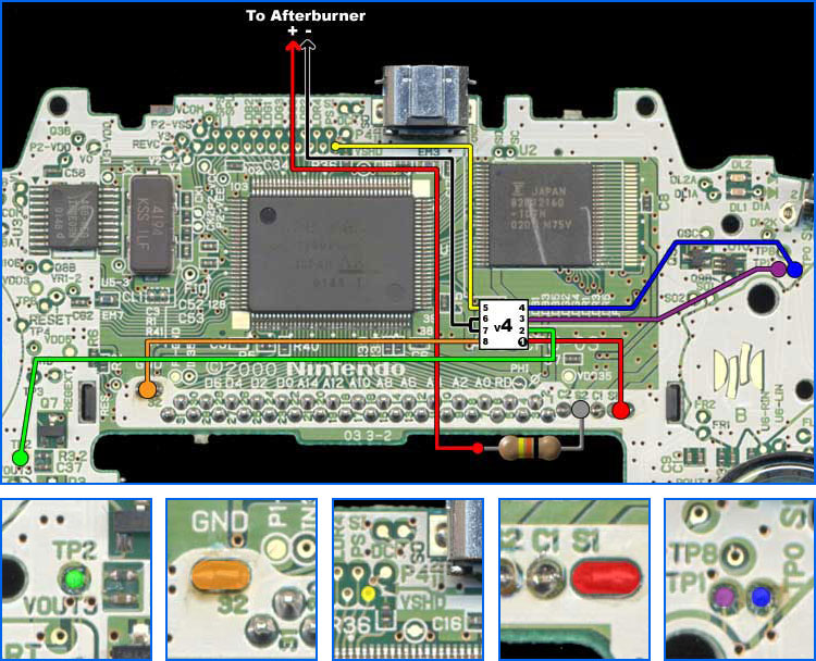
GBA Button Signals:
TP0- A
TP1- B
TP2- Select
TP3- Start
TP4- Right
|
TP5- Left
TP6- Up
TP7- Down
TP8- R
TP9- L
|
|
|
Chip Signals:
Pin 1- +3.3 volts (Chip Power)
Pin 2- "Enable" Input (Select)
Pin 3- "Darker" Input (B)
Pin 4- "Brighter" Input (A)
Pin 5- Sync Input
Pin 6- AB Out (-)
Pin 7- AB Out (-)
Pin 8- Ground |
 |
|
Installation Tips:
- Locate Pin 1 on the chip by looking for a dimple in one corner
- Stick the chip to the GBA board using double-sided tape first so it won't move around while soldering
- Cut off excess wire length
- Use low-wattage, fine-tipped soldering iron
- Use flux or rosin-core solder
- Don't hold the iron on the chip pins too long as you could damage the chip
- Don't hold the iron on the GBA board too long as you may lift the solder pad
- Don't connect a wire directly from Afterburner (-) pad to GND on the GBA board (as shown in Afterburner manual). This could damage the chip
- If alternate button assignments are desired, see button signal list for available connection points
|